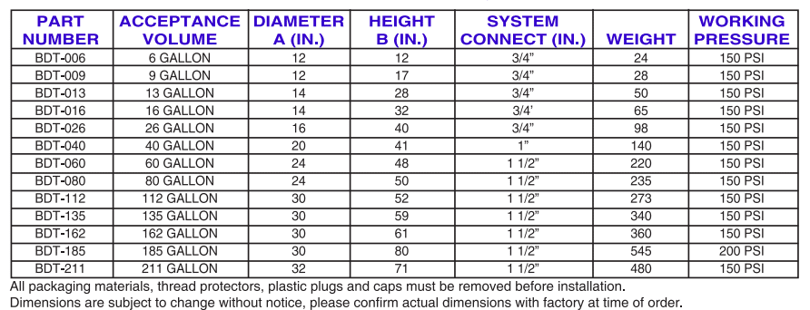
American Wheatley HVAC BDT Multi-Purpose Bladder Expansion tanks are pre-charged bladder expansion tanks constructed to the latest ASME standards.
They are designed for the storage of potable water for pressure boost systems, as well as typical cooling/heating applications. The system’s expanded water is constrained in a heavy-duty bladder preventing tank corrosion and waterlogging problems.
The factory set pre-charge for these tanks is 12 PSIG. The BDT Multi-Purpose Bladder tank is suitable for potable water applications.
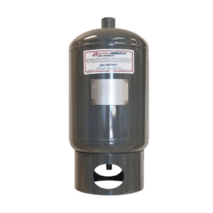
What does a Multi-Purpose Bladder Tank do?
Designed to absorb the expansion of fluids in typical hydronic systems, the BDT Multi-Purpose Bladder Expansion Tank is used in pressure-boost systems as well as the typical cooling and heating applications.
Bladder material is suitable for hot water applications. Installation of the tank will help eliminate constant pump use, prolonging pump life and unnecessary blowing of relief valves.
What are the features of a BDT Multi-Purpose Bladder Tank?
Features:
- Constructed in accordance with ASME Section VIII, Division I, Latest Edition
- Stainless steel system connection
- EPDM Bladder
- Full Acceptance Bladder Design / Replaceable
- Factory Air Charged to 12 P.S.I
- Maximum temperature 280F Intermittent
- Constructed of NSF 61 Compliant Materials
- Primed Exterior
Optional Features:
- Higher working pressure available
- Top entry
- “Bulls Eye” sight glass
- Seismic mounting (clips or legs)
- Painted Exterior, Epoxy Coatings
Is a Bladder Expansion Tank necessary?
An expansion tank is always highly recommended if you have a ‘closed-loop system’ caused by any kind of check valve or pressure regulating valve installed on your house’s water supply line.
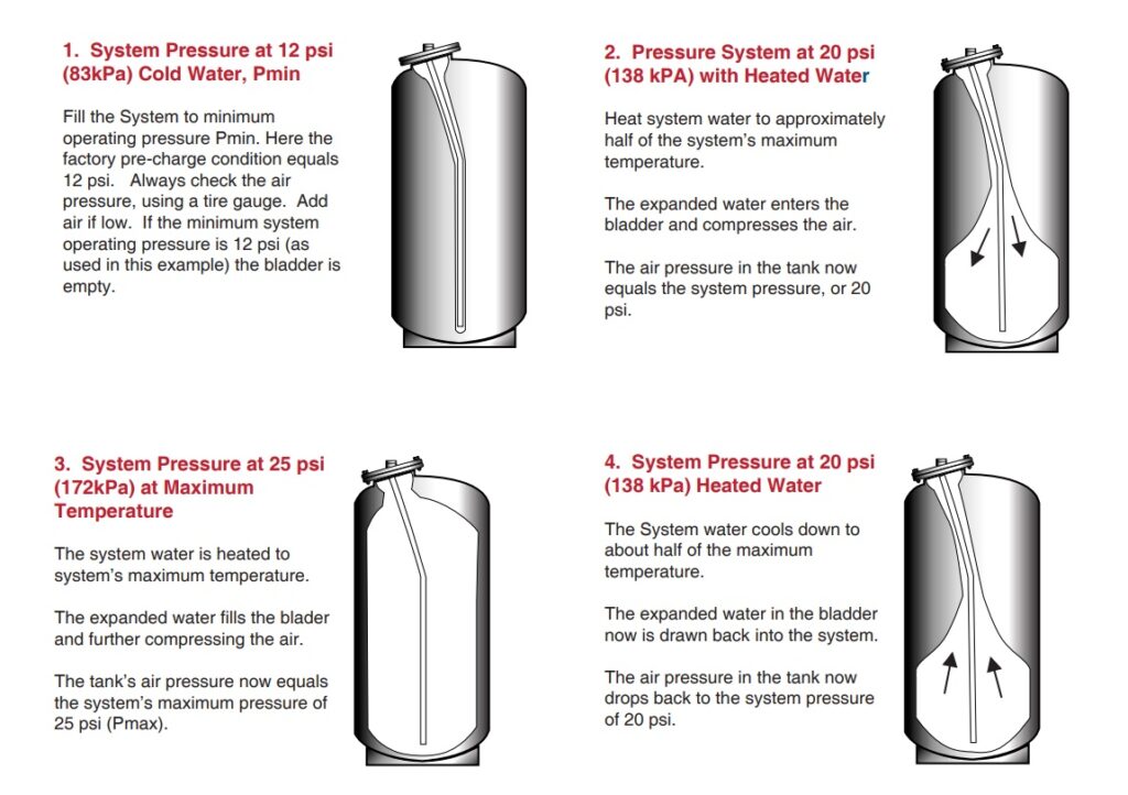
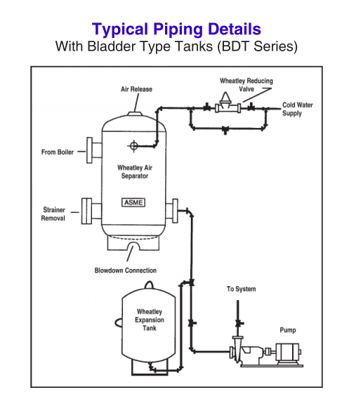
How do Multi-Purpose Bladder Expansion Tanks work?
How do I replace a bladder in a BDT Series Bladder Tank?
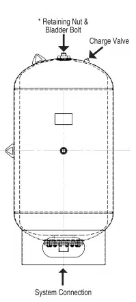
1. Isolate multi-purpose bladder type expansion tank from the system. Shut off automatic fill, valve, and drain boiler to release all system pressure.
2. Bleed system air charge through air charging valve. Remove air valve core at top of the tank and discharge remaining air.
3. Disconnect tank from the system.
4. Remove the bolted bottom flange. Prior to removal, mark mating flanges in order to match up properly when reassembling.
5. Loosen and remove the retaining nut on top of the tank. For tanks 26 gallons and smaller, proceed to step 6.
6. Using the chain block and a slight twisting motion, slide the bladder out of the tank. Remove the bladder retaining bolt from the inside of the bladder.
7. Clean up any remaining water, dry out the inside of the tank and clean out any remaining dirt or foreign particles. Check the inside of the tank for any sharp edges that may cut the bladder.
8. Place bladder bot inside new bladder secured with 1/4″ All Thread Rod threaded into the top of bladder bolt. Roll up the bladder as necessary and pull through the tank with a threaded rod.
9. Secure bladder bolt to the top of the tank with retaining nut. Hand tightens at this point. For tanks 26 gallons and smaller, proceed to step 10.
10. Position the bottom neck of the bladder in the bottom of the tank opening to act as gasket sealing surface for system connection.
11. Replace the bottom flange, align the marks and tighten the bolts evenly, using a star pattern.
12. Tighten all threaded and bolt connections.
13. Using compressed air source and pressure gauge, apply 10 psi air pressure to the flange connection then relieve pressure. These actions should ensure proper positioning of the replacement bladder within the tank.
14. Reassemble the air valve at the top and seal the hanger opening.
15. Pre-charge tank to fill pressure or minimum operating pressure.
16. Using soapy water, check the air valve, retaining bolt, and nut, and bottom flange joint for leakage.
17. Reconnect the system, open the fill-valve and check the operation of the tank. Always pre-charge the tank before completing this step.
Furnished and installed and shown on planes, American Wheatley BDT series, full acceptance expansion tank. The tank shall be constructed of carbon steel in accordance with ASME Section VIII, Division 1, latest edition. The tank shall incorporate a removable and replaceable heavy-duty EODN bladder. The tank shall be supplied with a 12 psi factory air charge. Tanks shall be constructed and ASME stamped for 150 psi working pressure at 240F. Tanks shall be supplied with an exterior high-grade red oxide primer finish. Vertical or horizontal installation is acceptable. Non-replaceable diaphragm-type tanks are not acceptable.
Of course, these are just a few examples of what we have to offer. We will be more than happy to help problem-solve and find you the correct buffer tank that fits your needs. Don’t hesitate to reach out to us today for more information and other buffer tank varieties!
